toto How to assemble your Origin Outdoor - Cornilleau Play-Style pool table

How to assemble your Origin Outdoor pool table

To assemble your Origin outdoor pool table, please refer to the explanations below. A minimum of two people is required at all stages to assemble your pool table. All the tools you will need to assemble your Origin pool table are provided. The use of a power screwdriver is strictly prohibited, as it could damage certain parts, making them unusable.

Before assembly

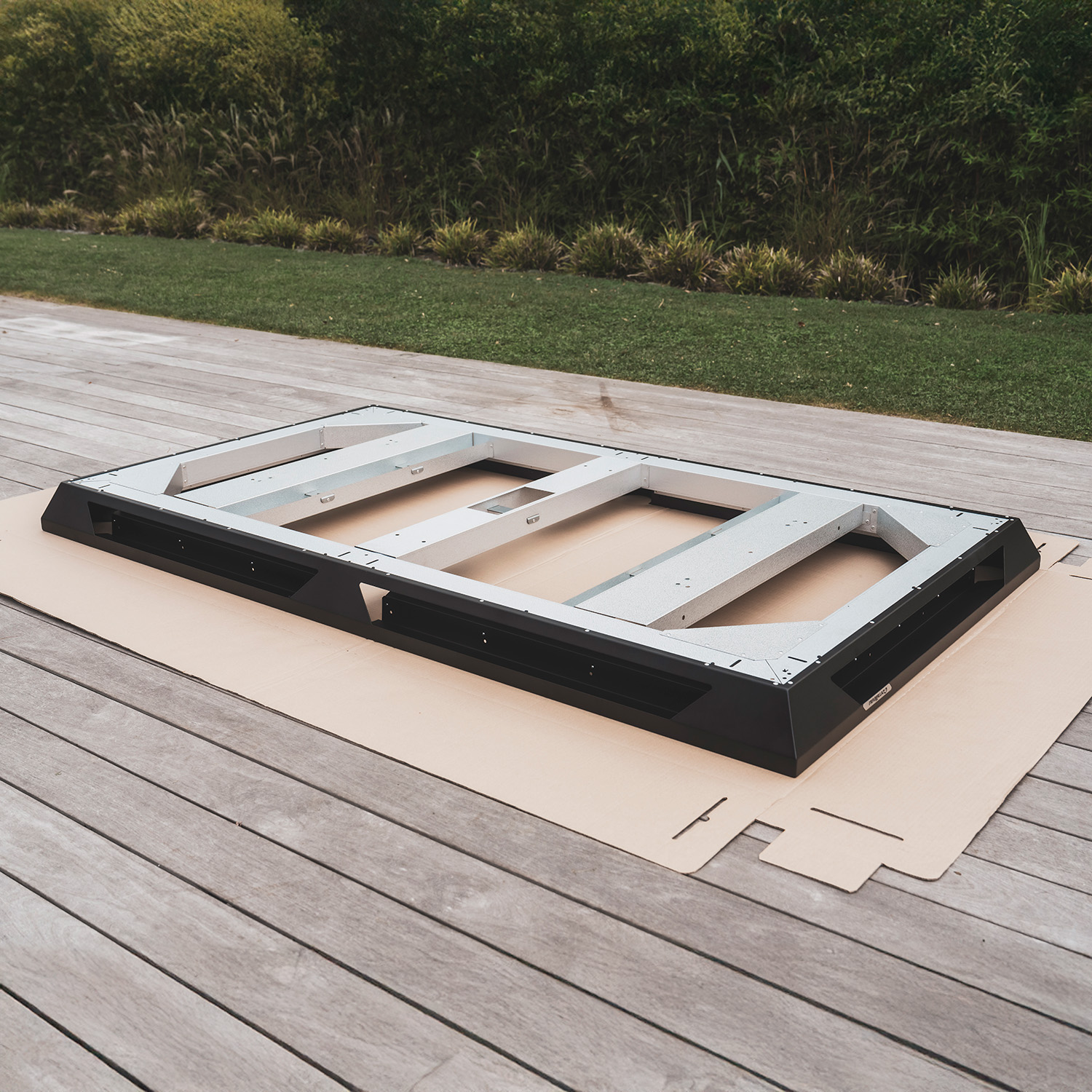
Cut open the side of the box. You can use the cardboard as a support while assembling your table. It will effectively protect the various parts and your floor from potential scratches.

Step 1

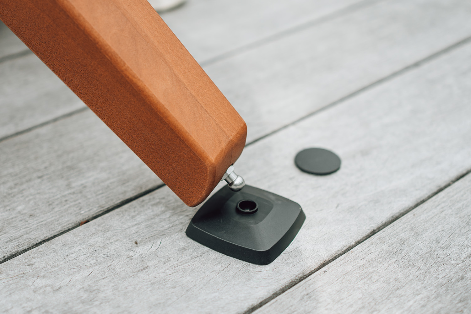
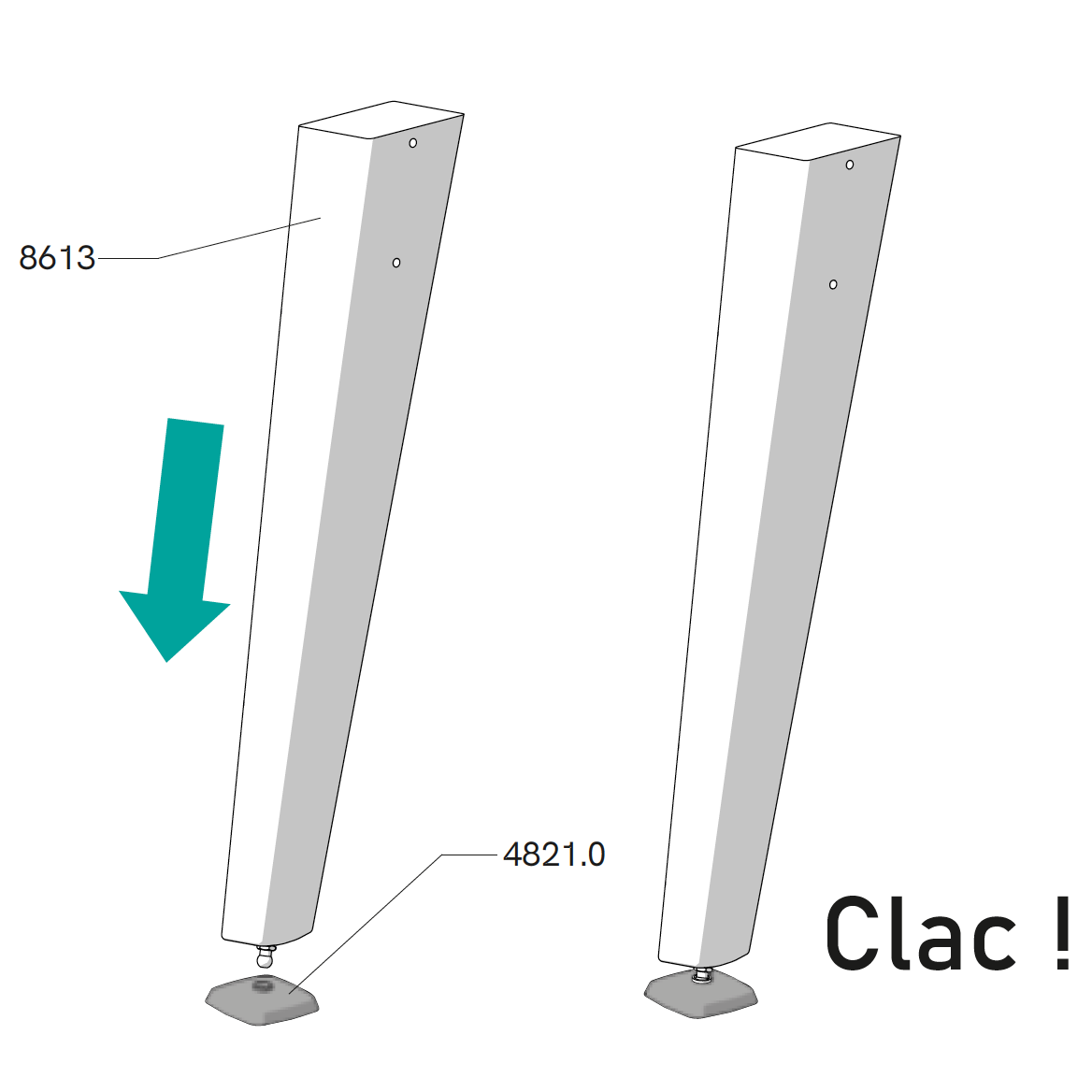
Take the levelling pad (Reference 4821.0), place it on the ground, and push the ball joint screw in until you hear a "click". Repeat this step with the other three legs.

Step 2

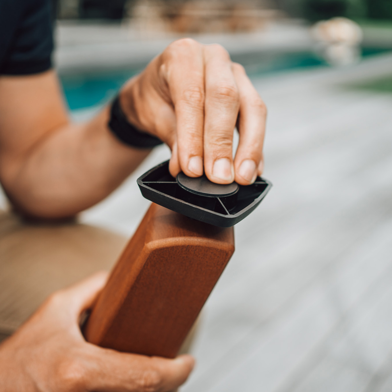
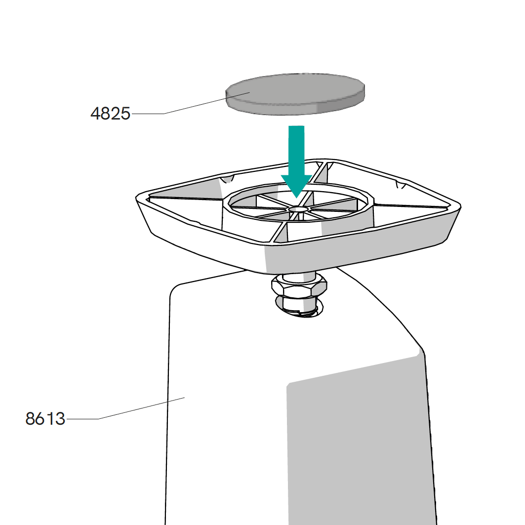
Stick the non-slip pad (Reference 4825) onto the levelling pad. Repeat this step for the other three legs.

Step 3

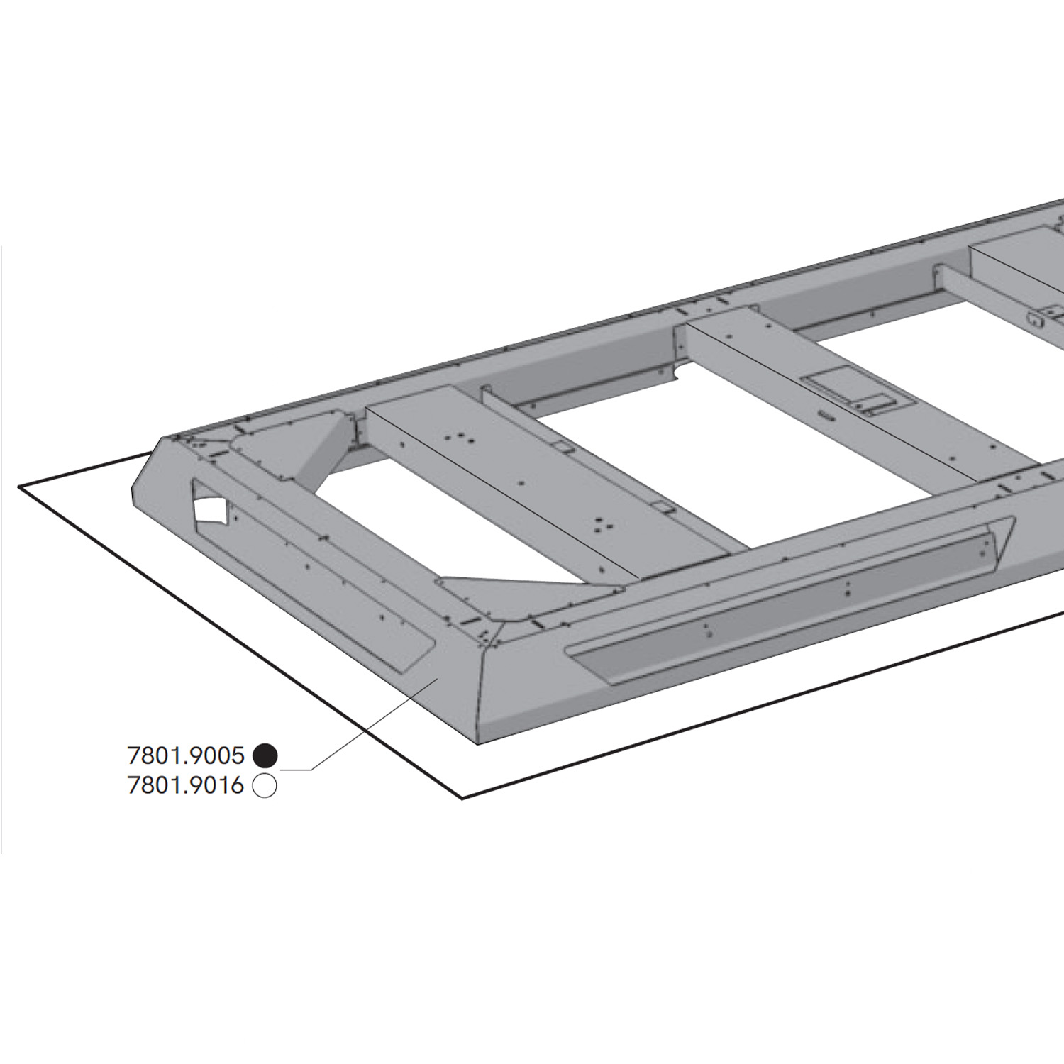
Place the pool table frame upside down on the unfolded cardboard to protect it during assembly.

Step 4

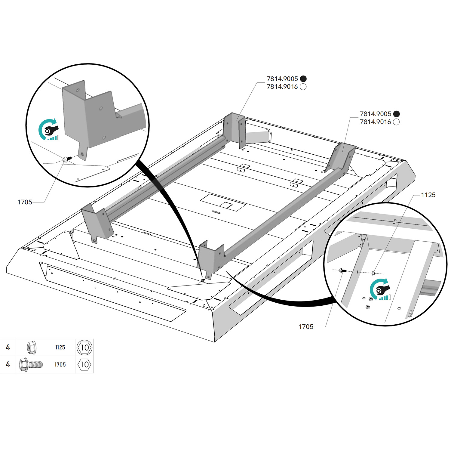
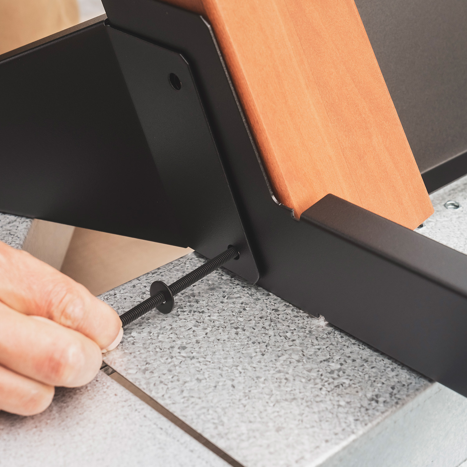
Position the side rails (7814) under the frame, with the open side facing inward. Align the hole in the rail bracket with the hole in the outer reinforcement, then insert the screw (1785) through both walls (the bracket tab and the outer reinforcement). Tighten firmly with the nut (1124) under the reinforcement.

Schéma d'assemblage de l'étape 20

Steps 5 & 6

Position the leg parallel to the side rails, paying close attention to the orientation of the leg (see video opposite). Place the leg horizontally into the bracket, then rotate it 90°. Next, align the holes in the leg with the holes in the side rail bracket. Repeat with the other three legs.

Schéma d'assemblage de l'étape 9

Step 7

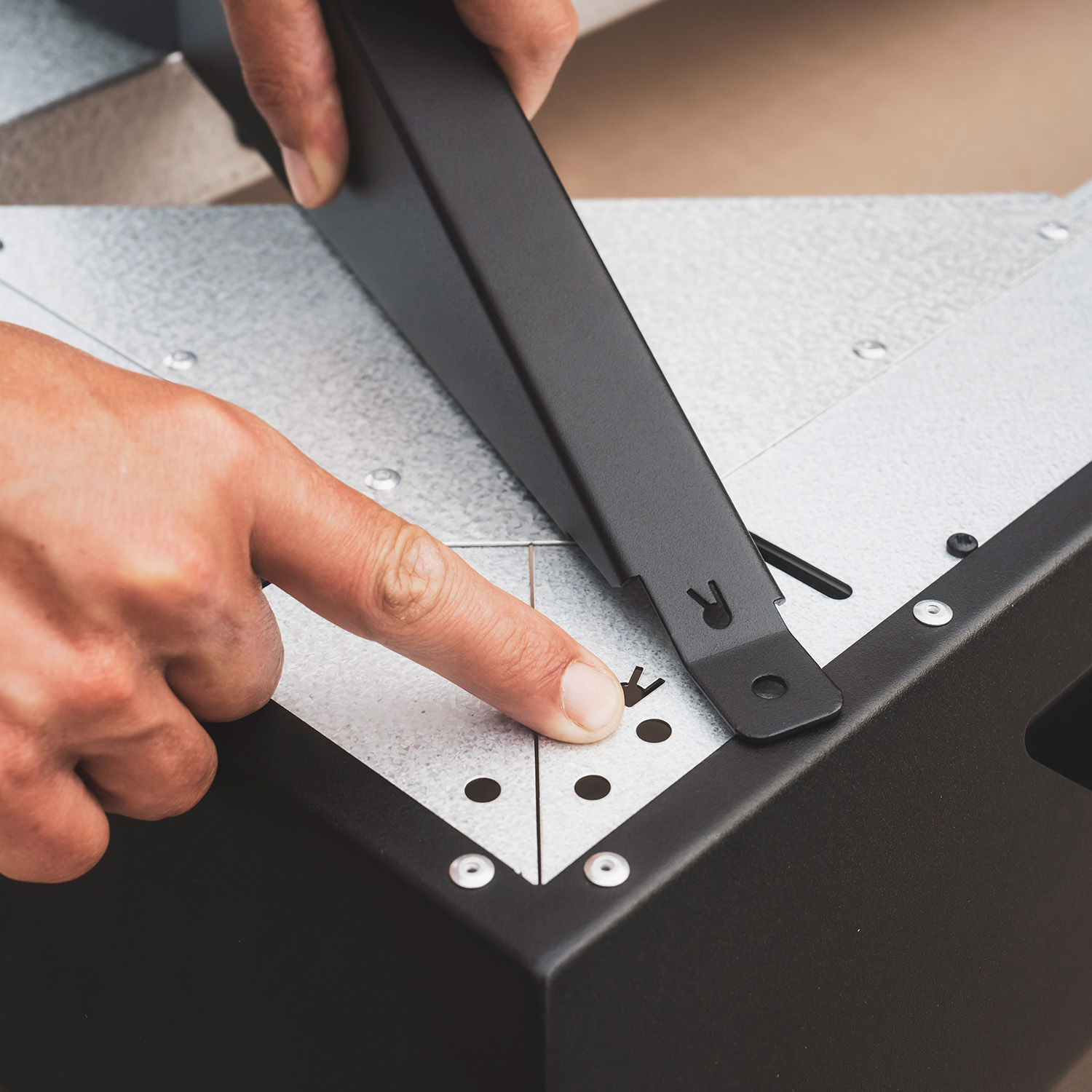
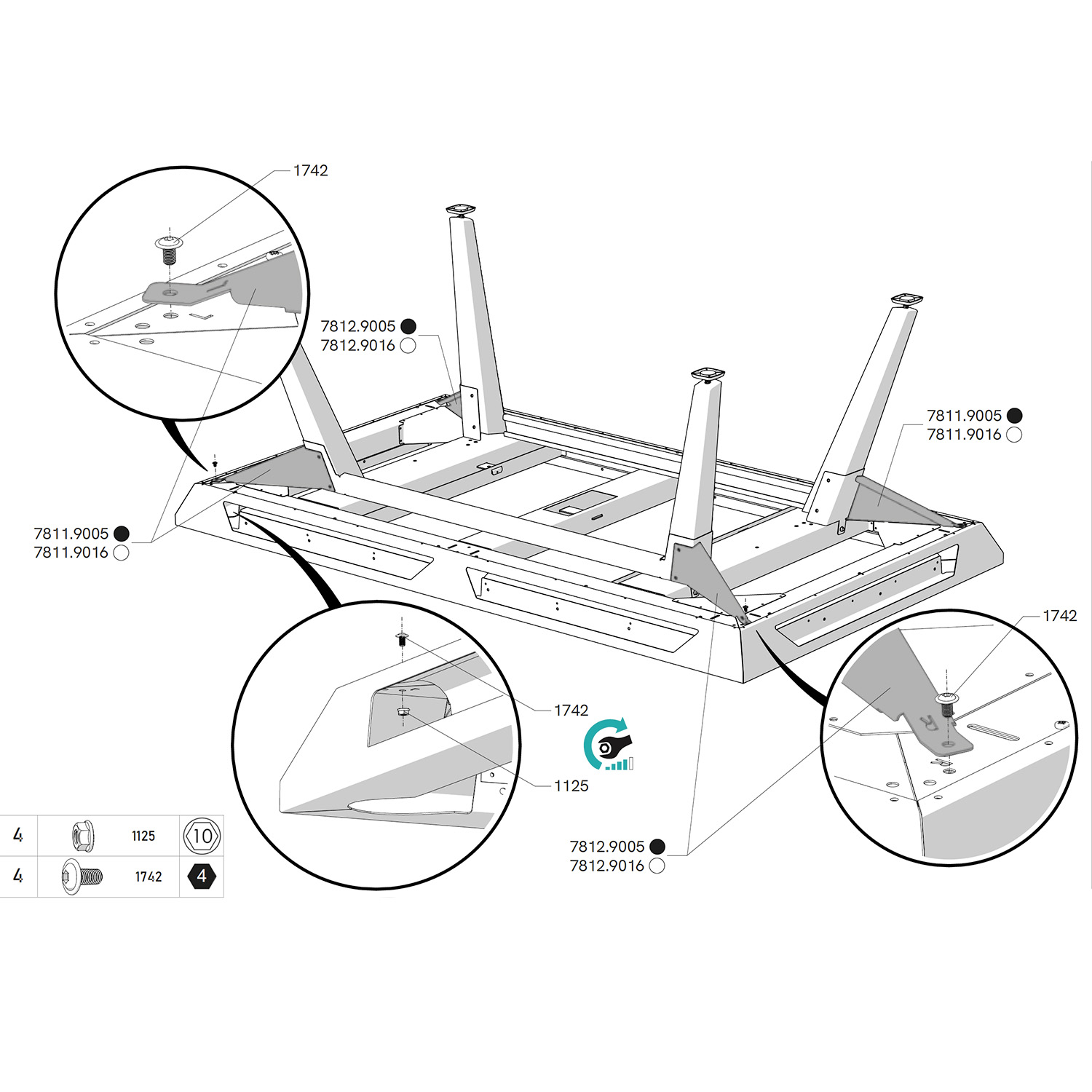
Position the struts (7812 and 7811) between the leg and the corner of the frame and align the holes with those of the bracket. Pay attention to the orientation: left and right are indicated on the struts and on the frame with L and R.

Insert the screw (1742) and tighten firmly with the nut (1124) inside the frame.

Step 8

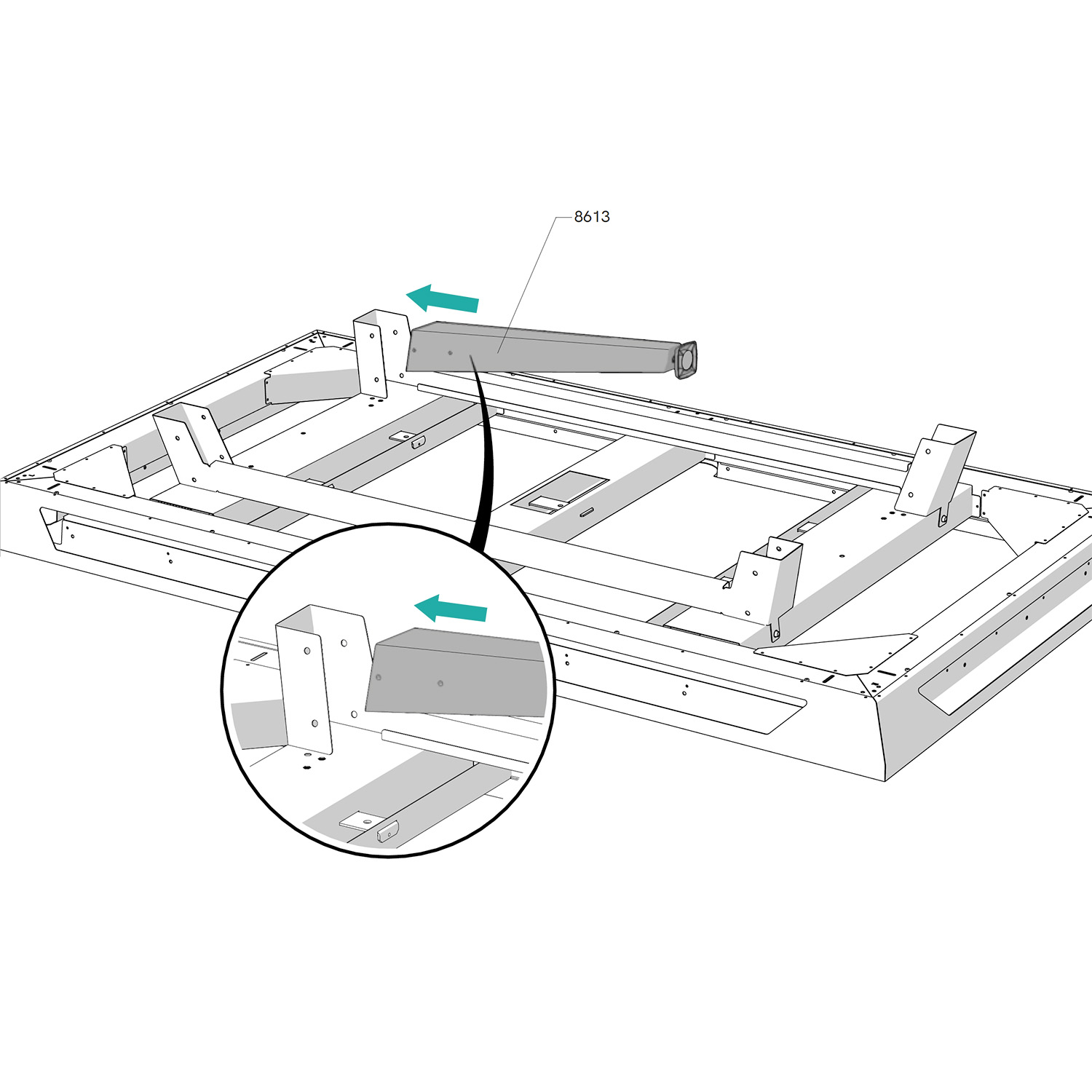
Slide the leg crossbar (7813) between the two side rail brackets. Pay attention to the orientation (see video opposite).

Schéma d'assemblage de l'étape 9

Step 9

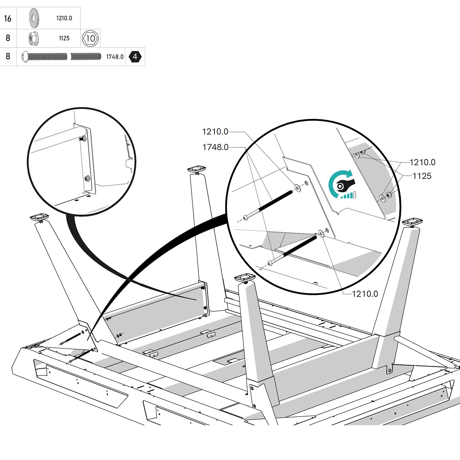
Place the washer (1210.0) on the screw (1748.0) and insert the screw through the strut, the bracket, the leg, the bracket again, and the leg crossbar to join all these elements together. Tighten firmly with the nut (1124).

Step 10

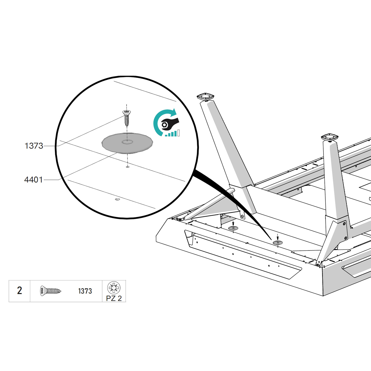
Take the triangle holders and screw them into the frame using the screw (1373), on one side or the other.

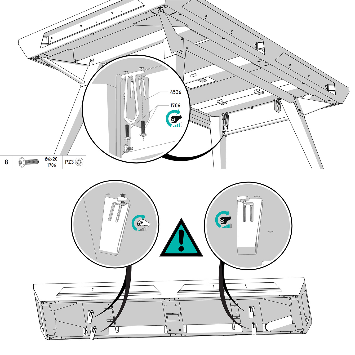
Screw the support brackets (4536) to the outer reinforcements using the screws (1706), paying attention to the orientation of the parts (see diagram above). Make sure to tighten them firmly on one side only and leave some play on the other.

Place the metal support (7861) into the opening of the plastic parts (4536).
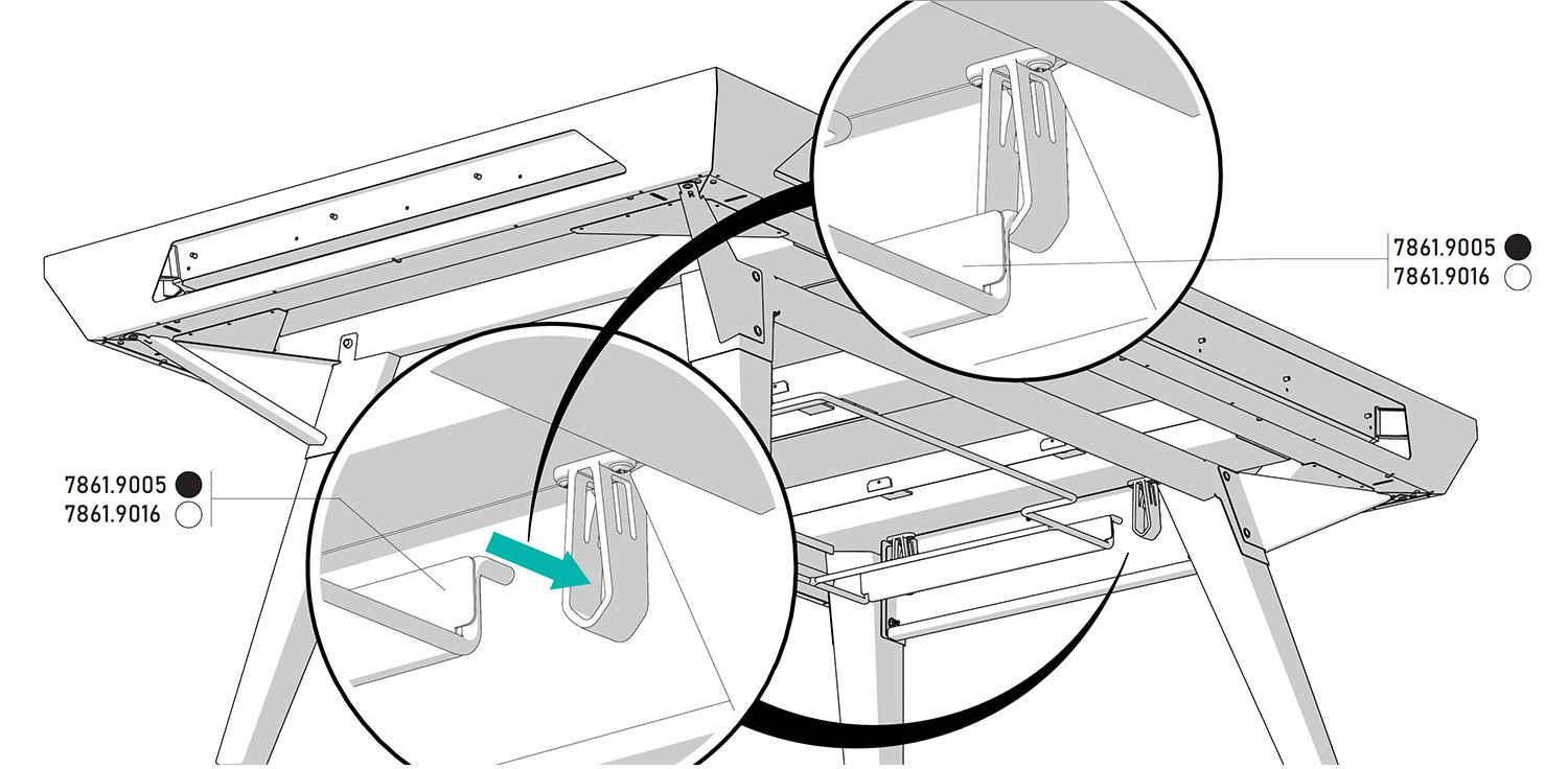
Tighten the screws on the side previously left with play to finalize the mounting of the support.
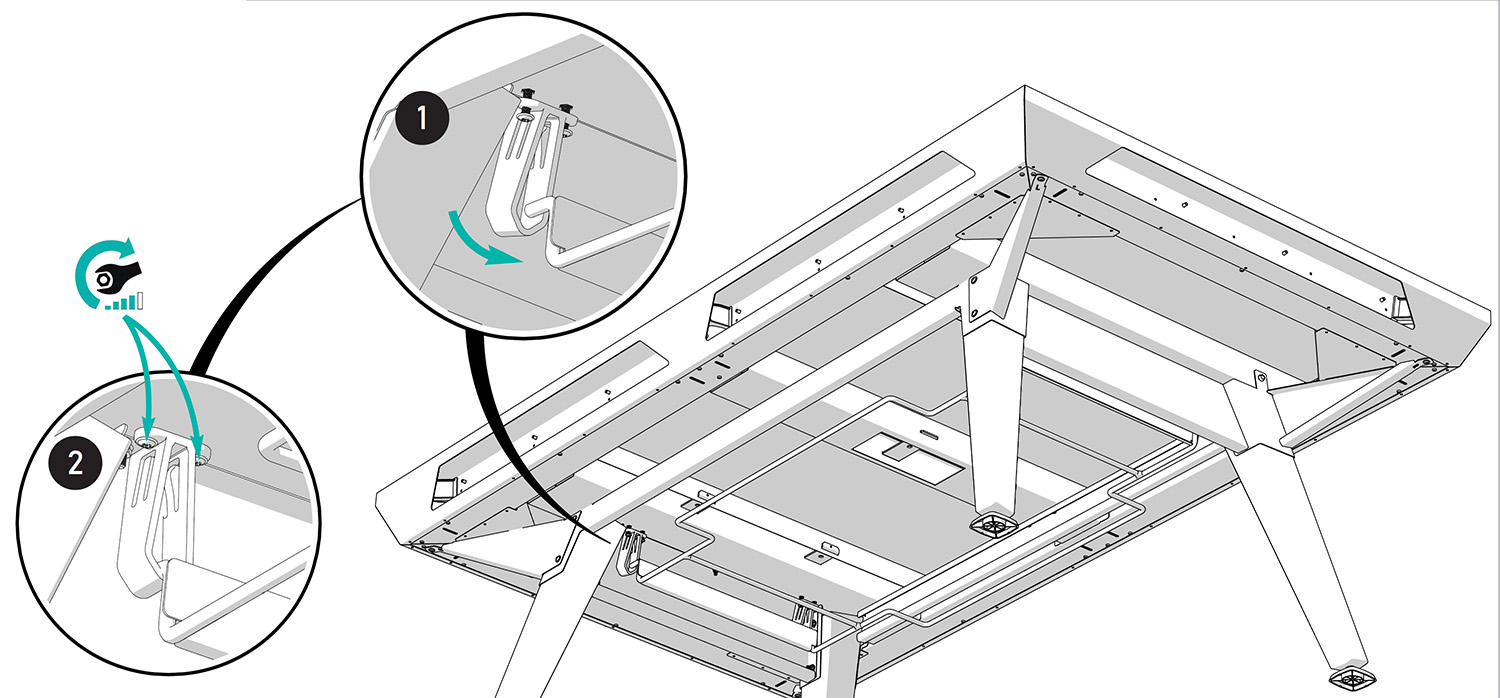
Screw the support brackets (4536) to the outer reinforcements using the screws (1706), paying attention to the orientation of the parts (see diagram above). Make sure to tighten them firmly on one side only and leave some play on the other.

Place the metal support (7861) into the opening of the plastic parts (4536).

Tighten the screws on the side previously left with play to finalize the mounting of the support.
Step 11

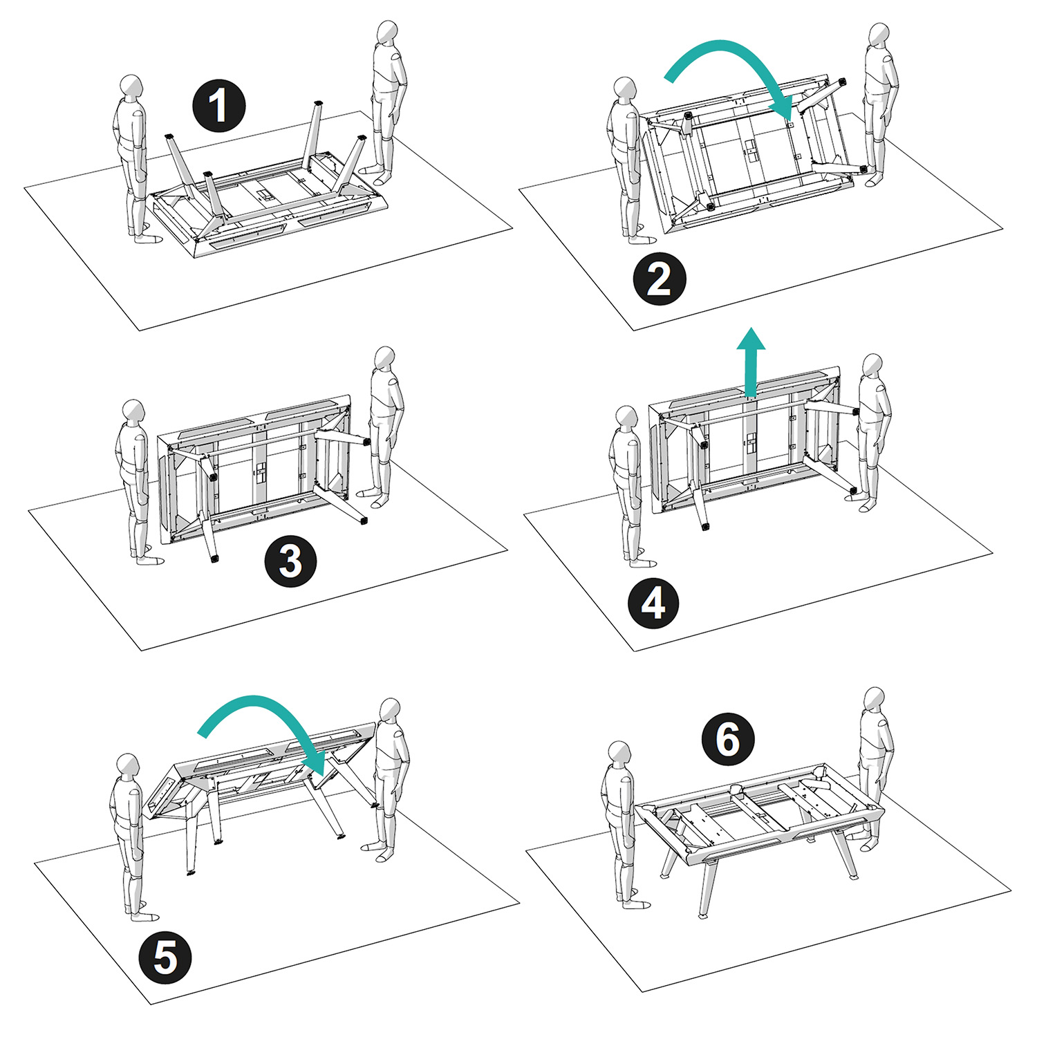
Turn the pool table over. Please note, more than two people may be required to lift it. Ideally, plan for four people.

Schéma d'assemblage de l'étape 20

Step 12

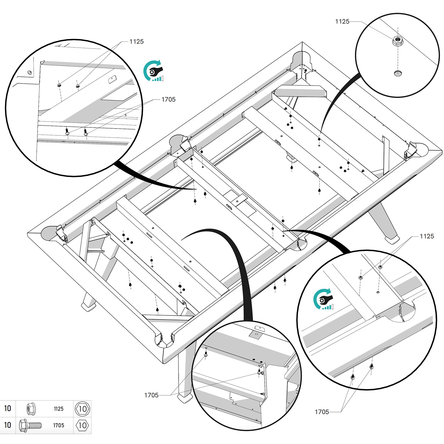
Secure the screws (1705) with the nuts (1124) to the central and outer reinforcements of the frame to finalize the assembly of the leg structure.

Step 13

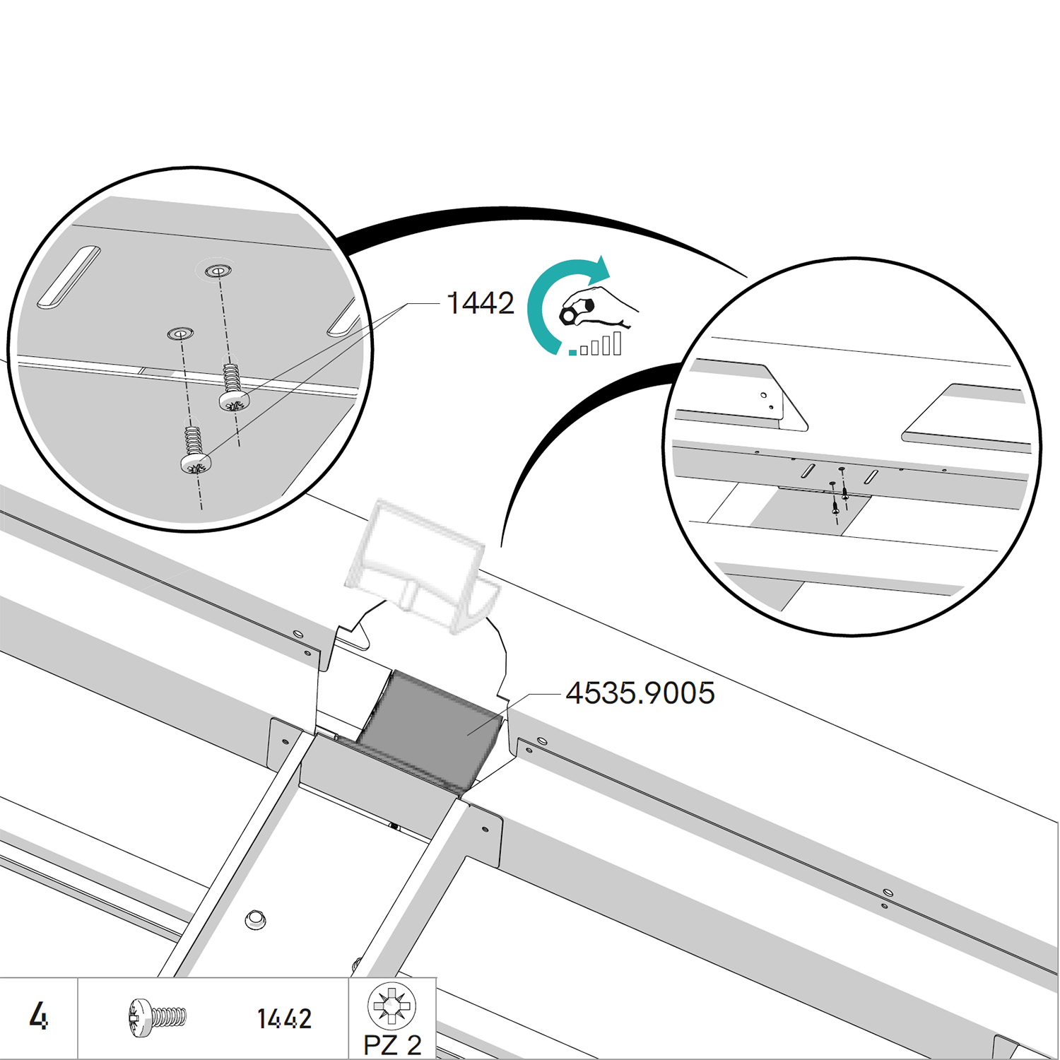
Insert the two central pocket liners (4535) into the central holes of the frame. Pay attention to the orientation (see video opposite).

Secure with the screws (1442) without over-tightening.

Schéma d'assemblage de l'étape 20

Step 14

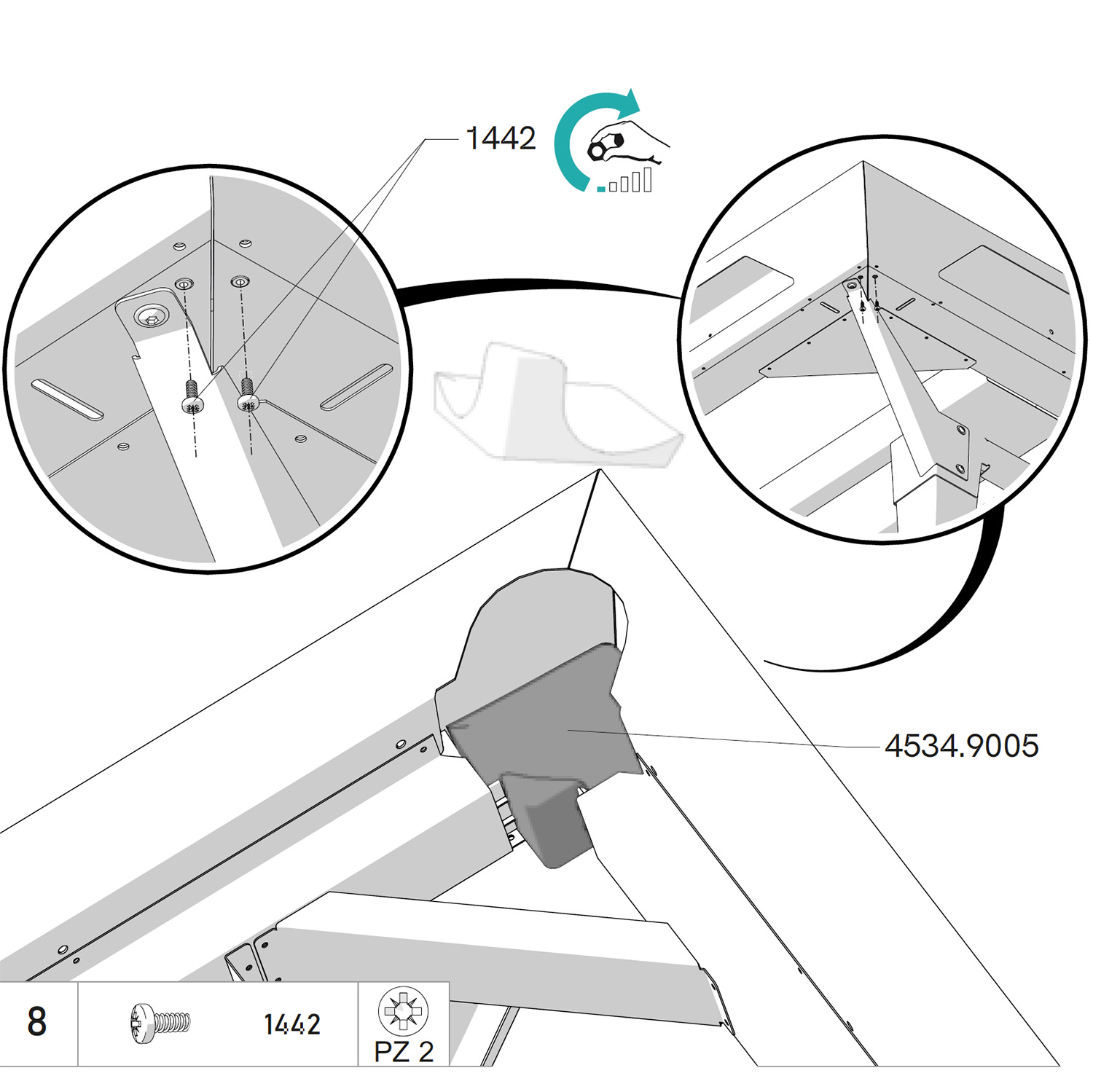
Insert the four corner pocket liners (4534) into the corner holes of the frame. Pay attention to the orientation (see video opposite).

Secure with the screws (1442) without over-tightening.

Schéma d'assemblage de l'étape 9

Step 15

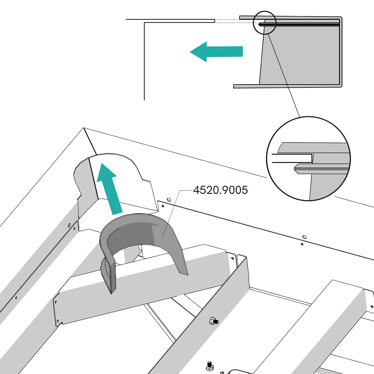
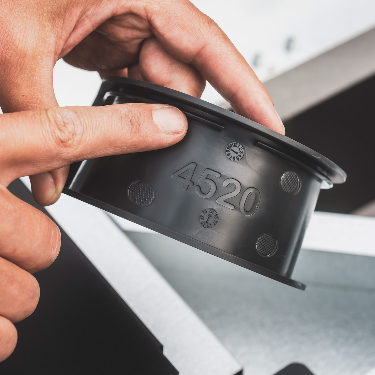
Insert the four corner edge trims (4520) into the frame. The groove must fit over the thickness of the frame's metal sheet.

Please note: if the trims are incorrectly installed, the slate will have to be disassembled again later.

Schéma d'assemblage de l'étape 20

Step 16

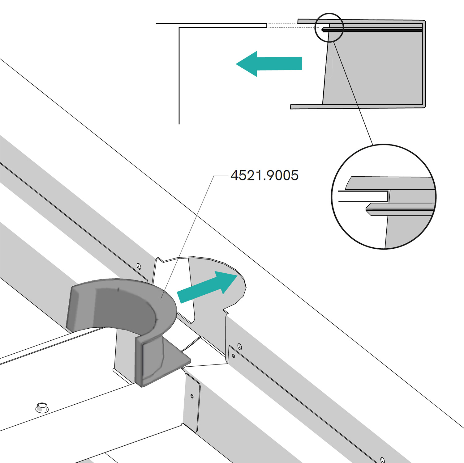
Insert the two central edge trims (4521) into the frame. The groove must fit over the thickness of the frame's metal sheet.

Please note: if the trims are incorrectly installed, the slate will have to be disassembled again later.

Step 17

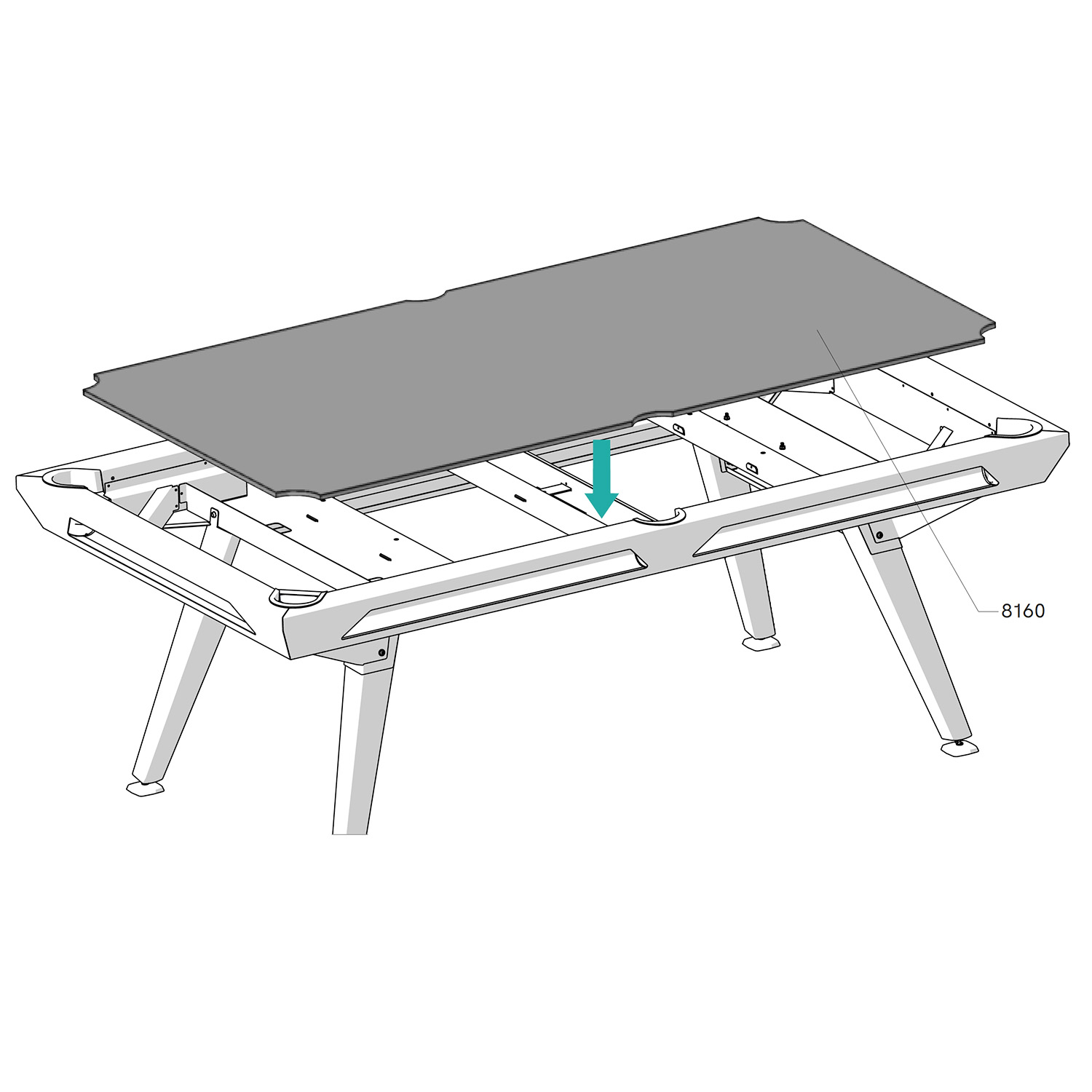
Place the slate (8160) at an angle onto the frame reinforcements. Use the pocket openings to lower the slate safely. Be careful not to pinch the edge trims.

Ensure that the slate is completely lowered inside the frame.

Schéma d'assemblage de l'étape 20

Step 18

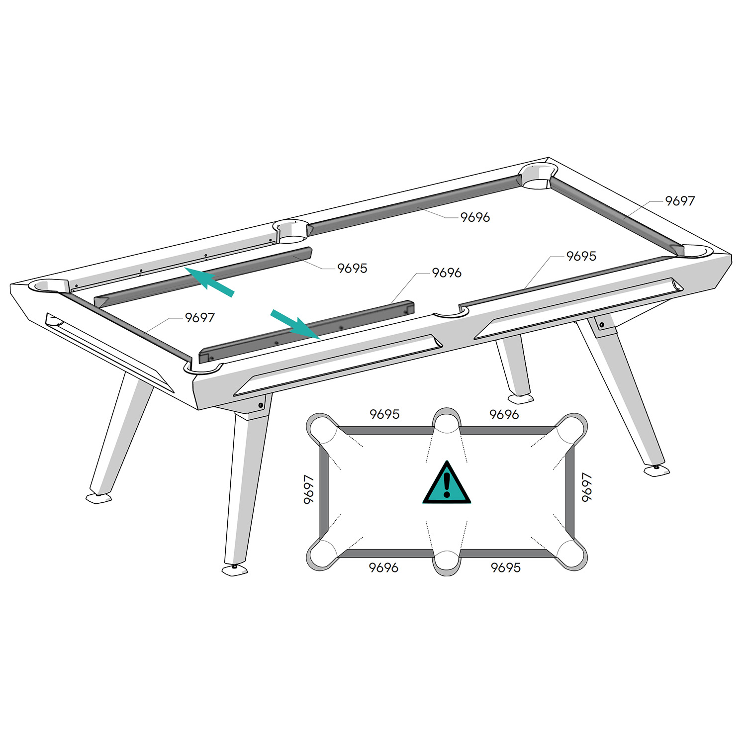
Insert the cushions (9695, 9696 and 9697) onto the inside sides of the frame.

Pay attention to the orientation; there are three types of cushions: two for the length and one for the width.

Step 19

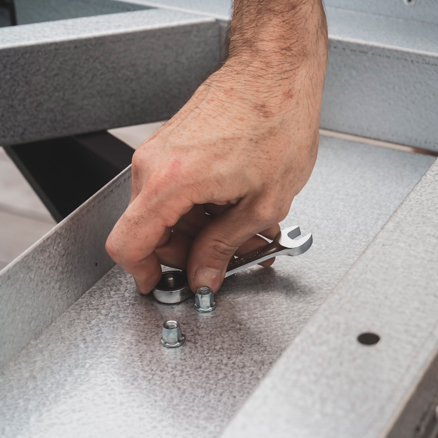
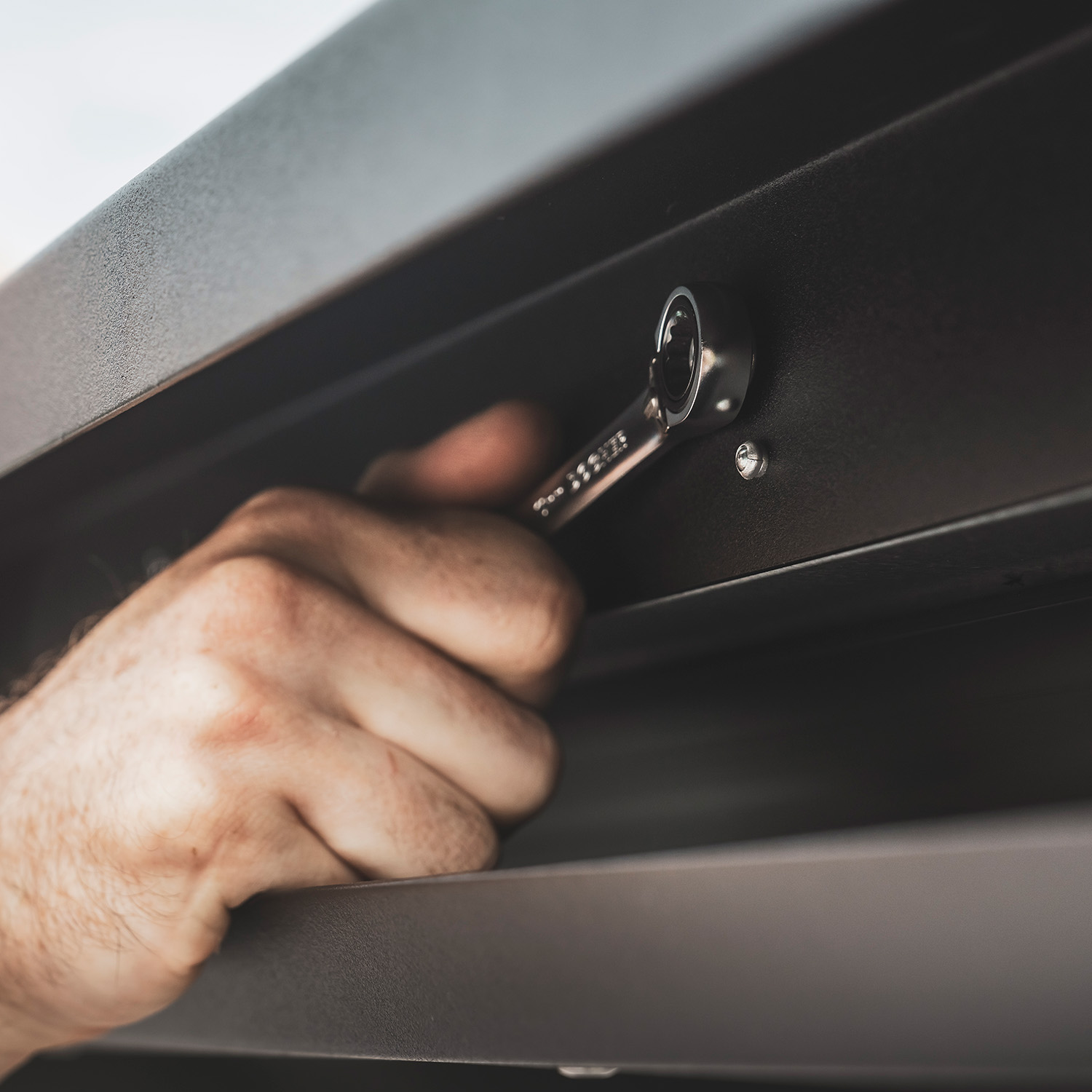
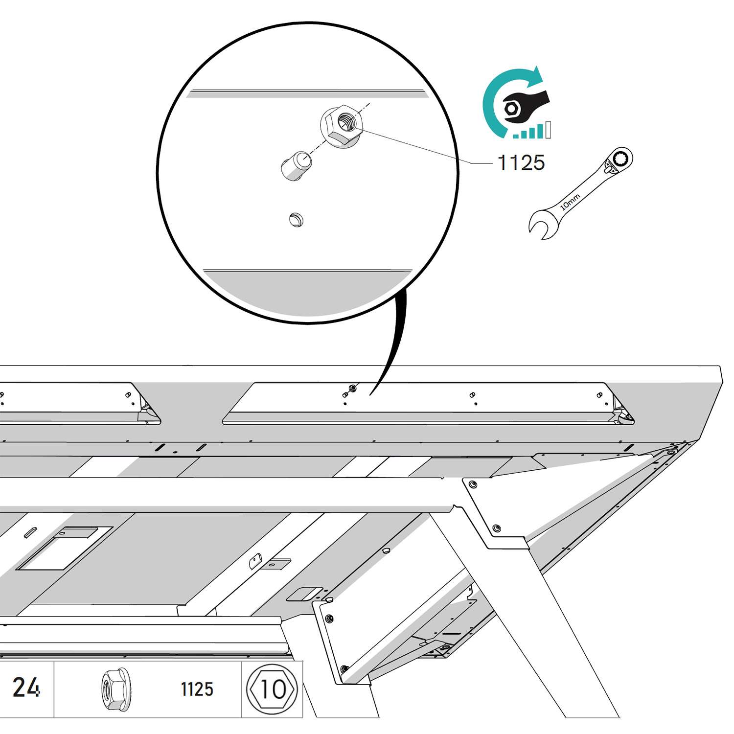
Firmly tighten the cushions with the nut (1124) using the provided ratchet wrench, inside the frame openings (ball return rails).

Steps 20 & 21

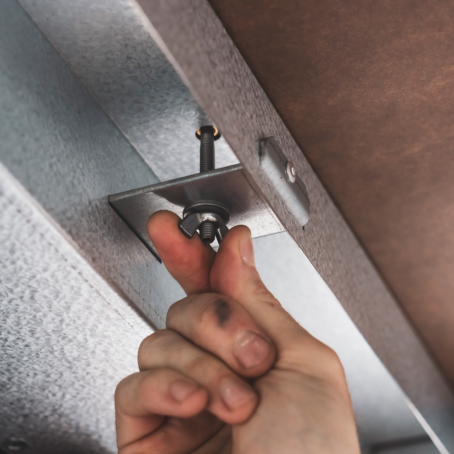
Insert the five screws (1896) using the provided wrench through the reinforcements under the pool table. Tighten by three full turns maximum.

Next, insert the washer (1261) and the wing nut (1165), then tighten gently until they make contact.

Caution: the insert may come out of the slate if the nut is tightened too hard.